
How to Choose a Step Up Transformer?
Choosing a Step Up Transformer is not simply a matter of matching two voltage figures. The right unit must also suit the load, operating pattern, installation environment, and protection scheme. A transformer that looks adequate on a nameplate may struggle with motor starting, fluctuating demand, or limited cooling. Small details matter.
Martin Heathcote, author of The J & P Transformer Book, is a respected technical reference in transformer engineering. Rather than inventing a direct quotation, this guide uses a practical selection maxim informed by that engineering approach: “Size the transformer for the real load and site conditions, not the voltage ratio alone.” It is a useful starting point, not a substitute for a qualified design review.
The sections ahead explain how to define the required input and output voltages, estimate kVA capacity, and account for continuous or intermittent duty. They also examine load inrush, efficiency, temperature rise, enclosure type, and installation location. For example, a unit beside a dusty workshop may need different protection from one inside a clean electrical room. A long cable run can also affect delivered voltage. These factors are easy to overlook.
No checklist can predict every site condition. That is worth admitting. Before purchase, confirm the equipment data, available supply, grounding arrangement, and applicable technical requirements with a qualified electrical professional. A careful choice can improve reliability and reduce avoidable operating problems. The best Step Up Transformer is the one that fits the actual application, not merely the nearest catalog rating.
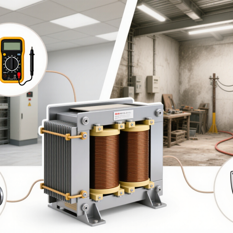
Understand the Function and Operating Principles of a Step-Up Transformer
A step-up transformer raises AC voltage through electromagnetic induction. Alternating current in the primary winding creates a changing magnetic field in the core. That field induces voltage in the secondary winding. The voltage ratio roughly follows the turns ratio: a secondary with twice as many turns produces about twice the voltage. Power is not multiplied; higher voltage generally means lower current for similar transmitted power, with some energy lost as heat.
That matters. To choose a unit, match its input voltage and frequency to the supply, then confirm the required output voltage, phase, and load in kVA. Allow for motor-starting surges and other short-duration peaks; a steady-load estimate alone can undersize the transformer. Check insulation class, cooling method, impedance, and installation conditions too. A hot, enclosed electrical room can reduce practical capacity. The awkward part is that “more capacity” is not always better: oversizing can increase no-load losses and cost.
Efficiency affects the wider system. The U.S. Department of Energy’s 2013 distribution-transformer standards analysis estimated cumulative energy savings of 3.63 quadrillion Btu over 30 years. That figure concerns regulated distribution transformers as a group, not the savings from one step-up unit. For a specific installation, compare the manufacturer’s loss data at expected loading, and have a qualified engineer verify protection, grounding, and voltage compatibility. Specifications can look tidy on paper; actual load behavior sometimes is not.
How to Choose a Step Up Transformer? - Understand the Function and Operating Principles of a Step-Up Transformer
| Selection factor | What to determine | Practical guidance | Illustrative example |
|---|---|---|---|
| Function and voltage ratio | Confirm the required primary and secondary voltages. A step-up transformer raises voltage from its input winding to its output winding. | For an ideal transformer, voltage ratio is approximately equal to the turns ratio: Vs/Vp ≈ Ns/Np. Actual output varies with load and transformer impedance. | A 240 V to 480 V transformer has a nominal 2:1 secondary-to-primary voltage ratio. |
| Load capacity (kVA) | Calculate the maximum apparent power the connected load will require, including expected operating conditions and starting demand. | For a single-phase load, kVA = V × A ÷ 1,000. For a balanced three-phase load, kVA = √3 × line voltage × line current ÷ 1,000. Select a rating that can carry the actual load without exceeding its limits. | A single-phase 480 V, 10 A load requires 4.8 kVA before considering application-specific starting or growth needs. |
| Phase and wiring | Match the supply and load: single-phase or three-phase, and the required winding connections and neutral arrangement. | Connection choices affect available line and phase voltages, grounding, and how the transformer behaves with unbalanced loads. Verify the connection diagram and system requirements. | A three-phase installation may use a delta-wye connection when a neutral is required on the wye side, subject to system design. |
| Frequency and waveform | Check the supply frequency and whether the source is sinusoidal or produced by power electronics. | Use a transformer designed for the system frequency. A transformer intended for 60 Hz should not automatically be assumed suitable for 50 Hz at the same voltage; follow its rated data and manufacturer instructions. | Specify 50 Hz or 60 Hz operation explicitly when comparing transformer ratings. |
| Impedance and voltage regulation | Review the transformer’s percent impedance and the amount of output-voltage change expected as the load changes. | Impedance influences voltage drop under load and the available short-circuit current. Compare the transformer data with load performance and the protection-system study. | A lower impedance can mean less voltage drop but higher prospective fault current; evaluate both effects. |
| Insulation and voltage rating | Check the rated winding voltages, insulation level, temperature limits, and suitability for the installation environment. | The transformer must be designed for the system voltage and applicable electrical standards. Higher secondary voltage requires appropriate insulation, clearances, and installation practices. | For an outdoor or high-voltage installation, confirm the specified insulation and environmental ratings rather than relying on nominal voltage alone. |
| Cooling and installation | Determine whether the transformer will be dry-type or liquid-filled and whether it will be installed indoors or outdoors. | Allow for heat dissipation, ventilation, ambient temperature, access, clearances, and any required containment or fire-safety measures. Follow local codes and installation instructions. | A ventilated indoor electrical room and an exposed outdoor site can require different enclosure and cooling provisions. |
| Taps and voltage adjustment | Check whether the transformer provides taps to compensate for supply-voltage variation or to adjust the output voltage. | Tap settings and adjustment methods differ by design. De-energize the transformer unless it is specifically designed and approved for on-load tap changing; follow its instructions. | A transformer with off-circuit taps may allow adjustment during a planned shutdown. |
| Efficiency and operating cost | Compare no-load and load losses, efficiency data, and expected operating hours. | Core losses occur while the transformer is energized; winding losses increase with load current. Efficiency depends on load, so use performance data at the expected operating point. | For equipment that remains energized continuously, no-load losses can matter even when the average load is modest. |
| Protection and grounding | Plan overcurrent protection, grounding, disconnecting means, and coordination with upstream and downstream equipment. | Protection must account for transformer inrush, rated current, fault current, and applicable electrical codes. A qualified electrical professional should verify the design. | Select protective devices using the transformer nameplate data and a system coordination study, not kVA alone. |
Note: The examples are illustrative only. Confirm ratings, connections, protection, and installation requirements against the transformer nameplate, applicable standards, local codes, and a qualified electrical professional’s design.